


CAD/CAM Lab Infrastructure
| Objectives: | |||
|
The CAD/CAM Lab is aimed at giving exposure to and enhancing the knowledge and skills of engineers involved in the operation use of CNC machines, CAD packages and for those who want to provide training to others in this area. It gives exposure and on hand experience in the field of CAD/CAM and CNC machines, Computer Integrated Manufacturing and Industrial Robots. |
|||
| Main Equipment Available | |||
|
 |
||
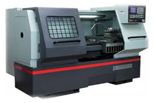 |
2. CNC Milling Centre CNC mills use computer controls that are able to translate programs consisting of alpha-numeric codes to move the spindle (or workpiece) to various locations and depths to cut materials. It has Automatics tool turret with 6 tools and Graphic simulation for product proving. |
||
|
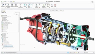
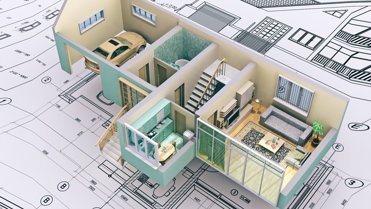
3. CREO (Pro/Engineer) Creo delivers the most scalable range of 3D CAD product development packages & tools in today’s market. Its variety of specific features, capabilities, & tools help engineers imagine, design, & create your products better.. This is versatile CAD/CAM software having main feature of Modeling and Design, Simulation and Analysis, Smart Connected Design, Model Based Definition, Assembling, Manufacturing, Automated Drafting |
 |
||
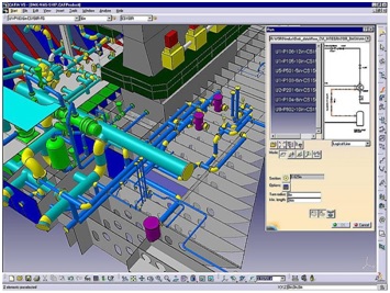 |
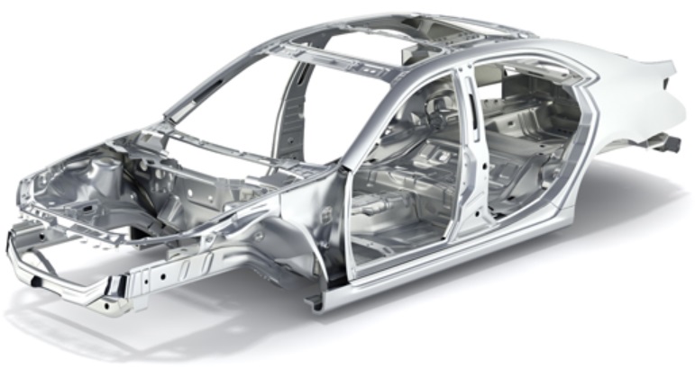
4. CATIA V5 CATIA® is the world’s engineering and design leading software for product 3D CAD design excellence. It is used to design, simulate, analyze, and manufacture products in a variety of industries including aerospace, automotive, consumer goods, and industrial machinery, just to name a few. It addresses all manufacturing organizations, from OEMs through their supply chains, to small independent producers. Once you know how to use CATIA, you are equipped with the most versatile design tool that’s applied in a multitude of industries. You will know how to design from scratch or reuse the working knowledge available from previous designs. |
||
|
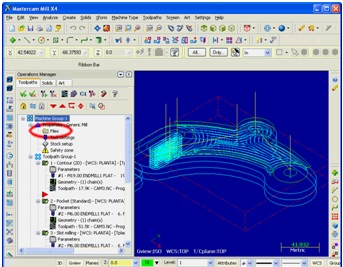
5. Master-CAM Master-CAM of CNC Software, Inc. is a suite of CAD/CAM software applications that is easy and intuitive to use, but maintains a depth of features to support the most complicated jobs. It has a comprehensive set of predefined toolpaths—including contour, drill, pocketing, face, peel mill, engraving, surface high speed, advanced multiaxis, and many more—enable machinists to cut parts efficiently and accurately. MasterCAM users can create and cut parts using one of many supplied machine and control definitions, or they can use Mastercam’s advanced tools to create their own customized definitions. Mastercam also offers a level of flexibility that allows the integration of 3rd party applications, called C-hooks, to address unique machine or process specific scenarios. |
 |
||
 |
6. AutoCAD AutoCAD is a commercial Computer-Aided Design (CAD) and drafting software application developed and marketed by Autodesk. With AutoCAD, you get access to seamless workflows, specialized industry toolsets, and new automations to help you achieve the ultimate productivity in 2D and 3D design. Get powerhouse performance, visualize Xref changes, enhanced Blocks capabilities, and version control to take your designs to the next level. Built for the way you work. Built for the future. |
||
|
7. Colour Plotter It prints professional-quality full colour scaled drawings, models as per CAD at your desk. This plotter is equipped with roll feeder to allow print larger lengths drawings easily with the width A0 size. |
 |
||
 |
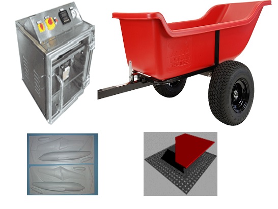
8. Sheet Metal Forming Sheet metal forming is a process where pieces of sheet metal are modified to its geometry rather than removing any materials. The applied process generates a force that stresses the material to deform. This in turn gives the possibility to bend or stretch the sheet to a variety of complex shapes. Sheet metal forming is quite common for making shaped components, from soda cans to automotive car bodies. In recent years, the demand for sheet metal parts with different shapes and properties has increased dramatically, due to the development of modern industries. Different techniques for forming high strength, low plasticity and difficult-to-form materials and complex-shaped parts have been developed in the past decades. |
||
|
9. Vacuumed forming Vacuum forming is a simplified version of thermoforming, where a sheet of plastic is heated to a forming temperature, stretched onto a single-surface mold, and forced against the mold by a vacuum. This process can be used to form plastic into permanent objects such as turnpike signs and protective covers. Normally draft angles are present in the design of the mold (a recommended minimum of 3°) to ease removal of the formed plastic part from the mold. Vacuum-formed components can be used in place of complex fabricated sheet metal, fiberglass, or plastic injection molding. There are numerous patterns one can make with vacuum forming. The most inventive way to use vacuum forming is to take any small item, replicate it many times and then vacuum form the new pattern to create a more cohesive form. |
|
||
|
|
9. Some Project Experiment a) Creating 2D and 3D Models using CAD b) CNC Part programming through CAD/CAM c) Machining of complex parts using CNC Machines d) Surface Machining e) Product proving f) Products produced from Vacuum formation g) Sheet metal enclosures for Electronic Equipment |
||